
Belt
Tensioning
Belt
Replacement
Motor
Replacement
Important: Power off printer
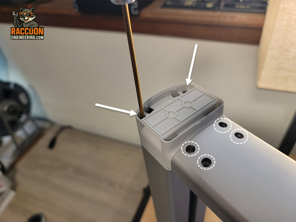
The Replacing the Z axis belt
Remove the decorative caps from the top of the gantry. Using a 2 mm allen wrench, remove the two 2 mm Allen screws securing each plastic housing. Next, remove the four 2 mm allen screws located on each side of the aluminum crossbar, as shown in Figure 1.
Once all of the mounting screws have been removed , carefully snap off the plastic end caps and loosen the Z axis adjustment lock screws on one side (Figure 2 - white circles). This will take tension off the belt. Now lift the aluminum crossbar off the gantry. Set the crossbar and all hardware aside. With the crossbar removed, the drive belt will be fully exposed, as shown in Figure 3.
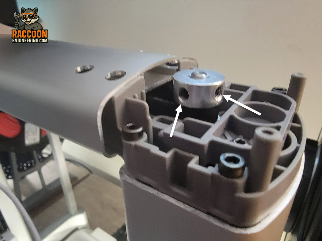
Each pulley is secured to its shaft with two set screws. Loosen the set screws on one pulley using the appropriate allen wrench, then carefully lift the pulley straight up and off the shaft. With the pulley removed, the belt can be lifted free and removed from the gantry assembly.
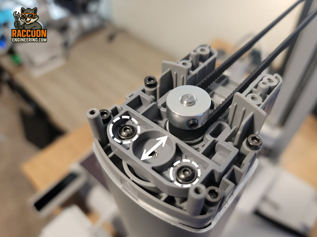
The new belt can be installed in the reverse order. Once installed the belt will need to be tensioned and the gantry X -axis will need to be fully releveled using the methods outlined below.
Tensioning the Z-axis belt
Unlike the other two axis on the printer, the Z-axis does not have a spring to assist with setting tension. It's a matter of loosening the locking screws (Figure 3 - white circles) and pulling the adjustment blocks outward. You should be able to do this with your fingers and prying with a tool is not needed or recommended. So just pull out firmly and lock down the screws.
After replacing the Z-axis belt, the gantry must be re-leveled to ensure proper printer operation. Begin by reinstalling the aluminum crossbar and securing it with the eight 2 mm Allen screws. Tighten all screws evenly to ensure the crossbar is fully seated.
Gantry Leveling
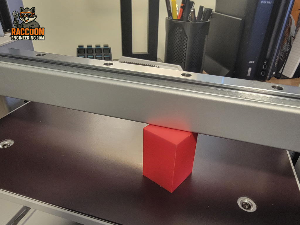
To check the gantry level, use a simple gauge block (Figure 4) or download and print the leveling gauge available on MakerOnline. The goal is to ensure the X-axis cross guide is the same distance above the build plate on both the left and right sides. Ideally, the height difference should be no greater than one standard layer height (approximately 0.2 mm).
Leveling the gantry is a trial-and-error process. With the pulley set screws loosened, carefully adjust the left or right side of the horizontal gantry up or down until both sides measure the same height above the build plate. Once the desired position is reached, tighten the pulley set screws to lock the adjustment in place. After tightening the set screws, manually move the gantry up and down several times to allow the belt and pulleys to settle into position. Measure both sides again and repeat the adjustment if necessary.
A note on lead screw lash. You should be able to grab the X axis bar and move it up and down slightly and feel play "lash" in BOTH lead screws. If not, more adjustment is needed so both have similar play.
When the gantry appears to be properly aligned, power on the printer and use the printer's control panel to move the X-axis up and down using the stepper motors. Recheck the height on both sides to verify the gantry remains level under powered operation. Make any final adjustments as needed.
Once leveling is complete, reinstall the plastic housings and secure each one with its two mounting screws. Finally, reinstall the decorative caps to complete the procedure.
Full Calibration after this process is recommended.