
Belt
Tensioning
Belt
Replacement
Motor
Replacement
Replacing Z Axis Stepper Motor
The Z-axis motor is located beneath the right-side gantry support. Because the motor is mounted inside the gantry assembly, the entire gantry must be removed before the motor can be accessed. While this adds a few extra steps to the procedure, it also provides an opportunity to inspect and clean the gantry components before reassembly. Carefully follow the instructions below to remove the gantry without placing unnecessary strain on the wiring or damaging any of the attached components. The printer base can be moved to the side as its not part of this service.
Begin by powering the printer off and turning it upside down. Remove
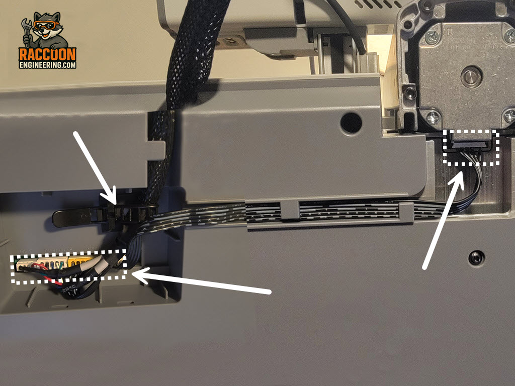
the wiring access cover from the bottom of the printer. Unclip the wiring restraint and carefully disconnect all of the gantry wiring connectors (Figure 1). Also disconnect the cable from the Z-axis motor where it plugs into the bottom of the gantry. Take note of the wire routing, as the cables should be returned to their original locations during reassembly.
Next, remove the inner gantry covers. Using a 4 mm Allen driver, remove the eight gantry mounting screws (four on each side). Once all of the fasteners have been removed, carefully lift the complete gantry assembly off the printer and place it on a clean work surface.
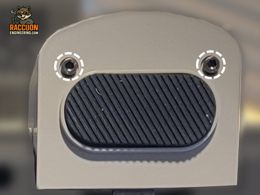
On the right side of the gantry, remove the decorative lower cover with the attached rubber foot (Figure 2). This cover is secured with two 2.5 mm Allen screws. After removing the screws, slide the cover outward to disengage it from the frame. This only needs to be done on the motor side.
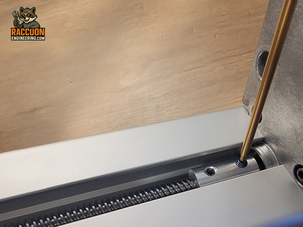
With the base cover removed, locate the shaft coupler inside the gantry connecting the stepper motor to the Z-axis lead screw (Figure 3). The coupler is secured with four set screws—two lock the lead screw and two lock the motor shaft. Note: You will have to rotate the shaft to get at the second screw. Only loosen the two lower set screws that secure the motor shaft. This will allow the coupler to separate from the motor while leaving the lead screw undisturbed.
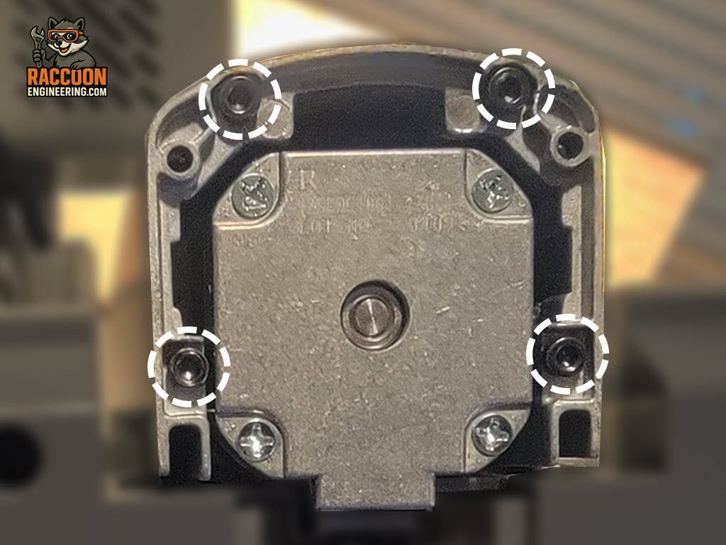
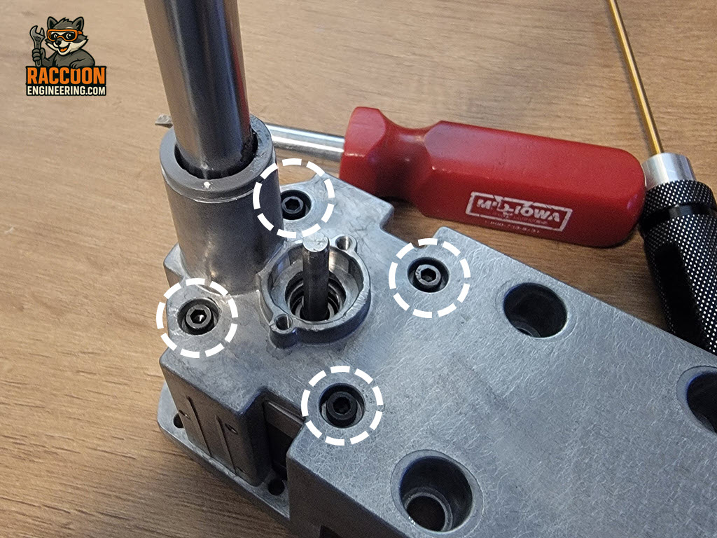
Turn your attention to the bottom of the gantry. Remove the four screws that secure the lower frame to the vertical aluminum extrusion (Figure 4). Once the screws have been removed, carefully slide the lower frame out of the extrusion just far enough to gain access to the upper motor mounting screws.
Remove the motor mounting screws shown (Figure 5) and lift the motor out of the mounting frame. Install the replacement motor in the same orientation as the original and tighten the mounting screws securely.
Reassemble the gantry by reversing the disassembly procedure. When reinstalling the shaft coupler, make sure one of the set screws aligns with the flat on the stepper motor shaft. Tightening a set screw against the flat is critical to prevent the shaft from slipping during operation.
After the gantry has been reinstalled on the printer, reconnect all wiring and secure the cable restraint. Verify that all gantry harness connectors are fully seated and that no wires can or get pinched. Reconnect both ends of the X axis motor cable.
Finally, adjust the Z-axis belt tension by following the procedure in the Belt Tensioning section. Once the belt has been properly tensioned, level the X-axis gantry before performing a full printer calibration. This calibration is required to ensure proper printer operation after the motor has been replaced. Instructions for leveling the gantry and tensioning can be found here.
A note on lead screw lash. You should be able to grab the X axis bar and move it up and down slightly and feel play "lash" in BOTH lead screws. If not, more adjustment is needed so both have similar play.