
Belt
Tensioning
Belt
Replacement
Motor
Replacement
This procedure covers replacement of the X-axis belt on the
Power off the printer before beginning.
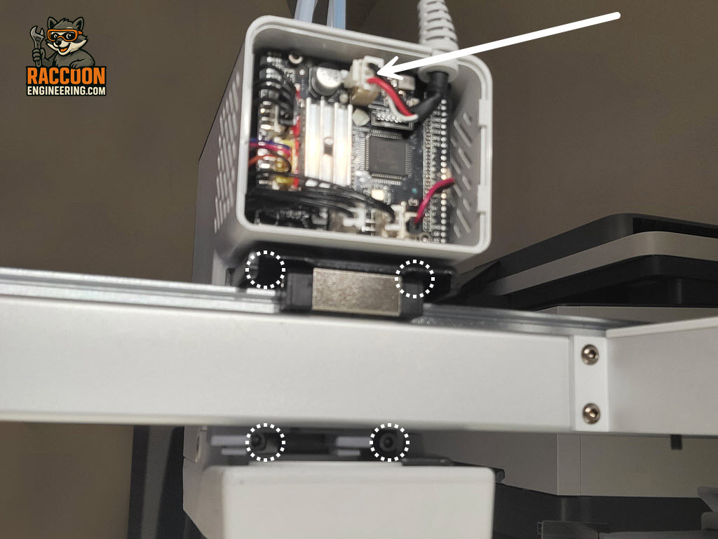
Start by snapping off the rear printhead cover and disconnecting the wiring harness indicated by the arrow in Figure 1.
Using a 2.5 mm Allen driver, remove the four screws (white circles) securing the printhead to the carriage. Carefully lift the printhead free and set it aside in a safe location (Figure 1).
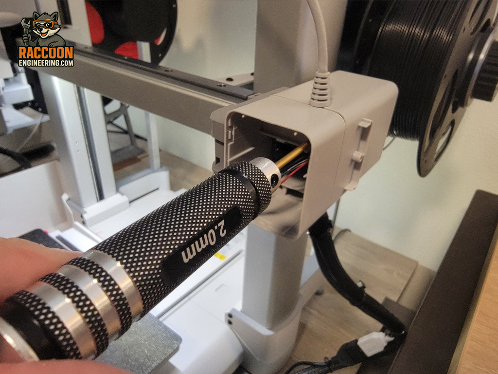
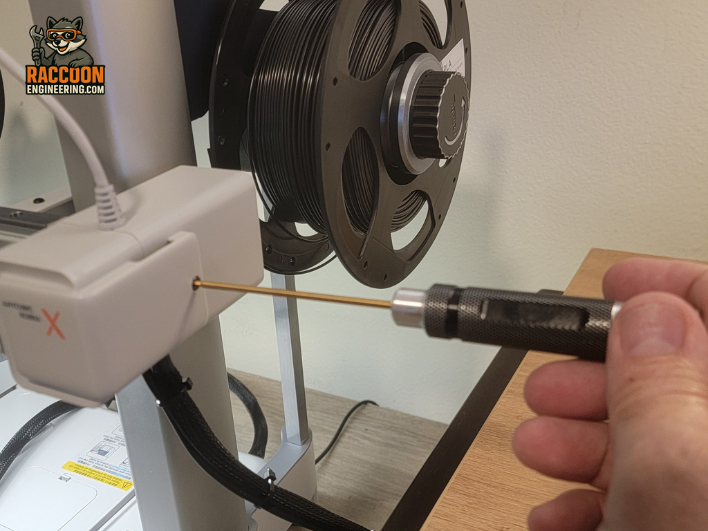
Next, remove the right-side front camera housing as described in the Motor Replacement section. In summary, remove the single screw on the right side and the three 2 mm screws hidden beneath the snap-on cover. Carefully disconnect the camera cable, noting the orientation of the connector for reassembly.
Removing this housing provides the clearance needed to route the new belt over the motor pulley and back to the carriage (Figure 5).
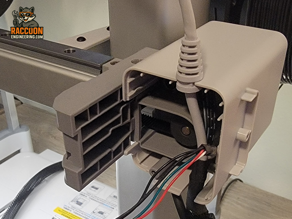
With the printhead removed, the two belt ends are visible where they attach to the underside of the printhead carriage (Figure 5).
Using a 2.5 mm Allen driver, remove both belt connectors from the carriage. Before removing the belt, carefully note its orientation. The toothed side of the belt must face inward toward the pulleys as shown in Figure 5. Installing the belt backwards will prevent proper operation.
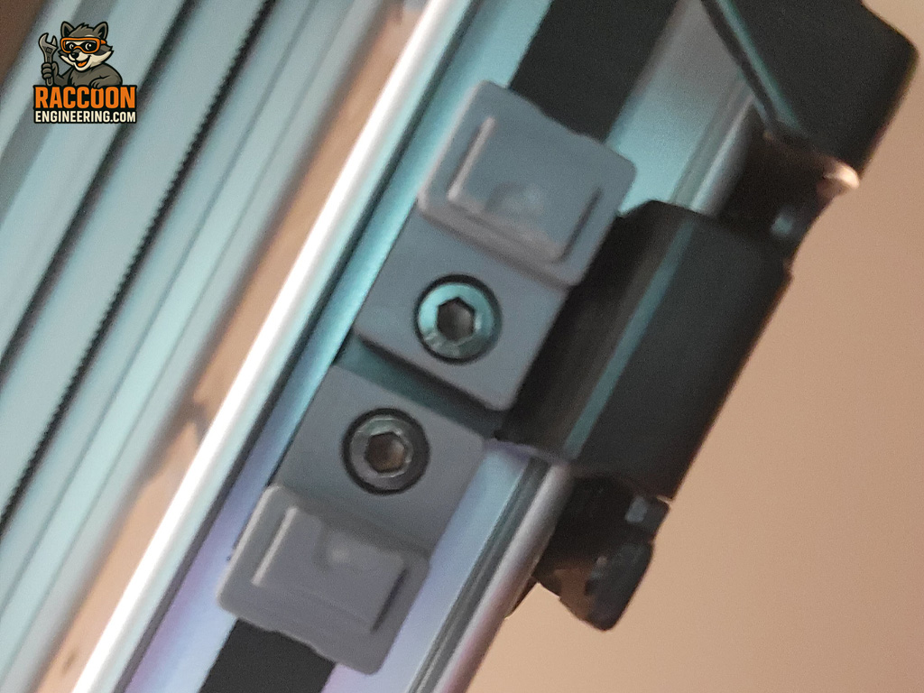
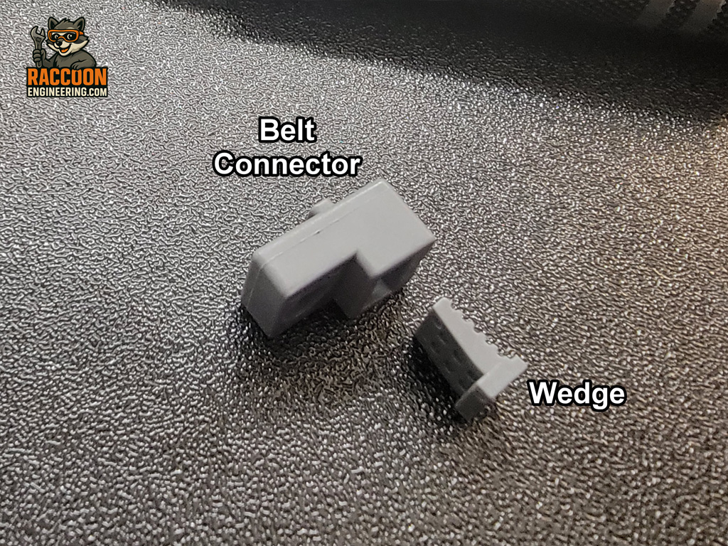
Each belt is secured inside its connector with a small wedge. Using a small flat-blade screwdriver, carefully pry the wedge from the connector and remove the belt. Figure 7 shows the connector and wedge separated.
To install the replacement belt, remove the tensioner assembly on the left side of the gantry. Loosen and remove the tension locking screws on the top and rear of the tensioner, then slide the complete tensioning assembly out of the gantry.
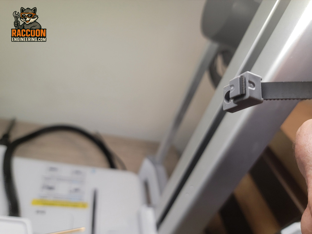
Route the new belt through the gantry, around the motor pulley on the right, and around the tensioning idler on the left. Verify that the toothed side of the belt faces inward toward both pulleys throughout its entire path.
Insert each end of the belt into its connector and reinstall the retaining wedges in the same orientation shown in Figure 7. Make sure the wedges are fully seated so the belt cannot pull free.
Reattach both belt connectors to the underside of the printhead carriage. The first connector installs easily, while the second typically requires pulling the belt tight to align the mounting holes.
Adjust the belt tension using the procedure described in the X Axis Belt Tensioning section.
Reinstall the right-side carriage housing, reconnect the camera cable, and reinstall the printhead using the four mounting screws.
Before applying power, manually slide the printhead carriage from one side of the gantry to the other. It should move smoothly with consistent resistance and no binding or rough spots. If any binding is present, recheck the belt routing and verify that the belt is seated correctly on both pulleys.
Once proper movement has been confirmed, power on the printer and perform a full calibration to verify correct operation.