
Overall
Printer
Inside
Base
Compete
Printhead
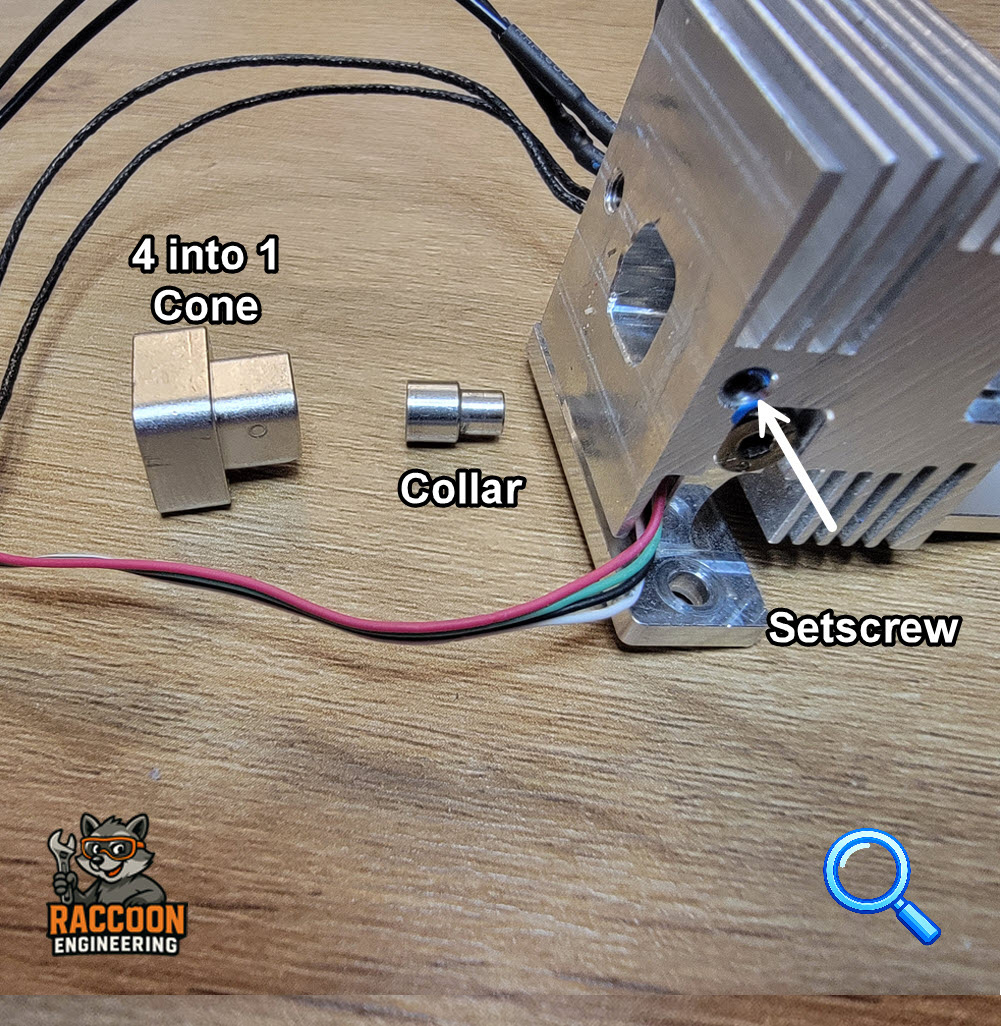
4 into 1 cone (and collar)
The cone and collar mount in the top of the heat sink in the orientation show. The collar goes in first and the 4 into 1 cone is locked in place with setscrew.
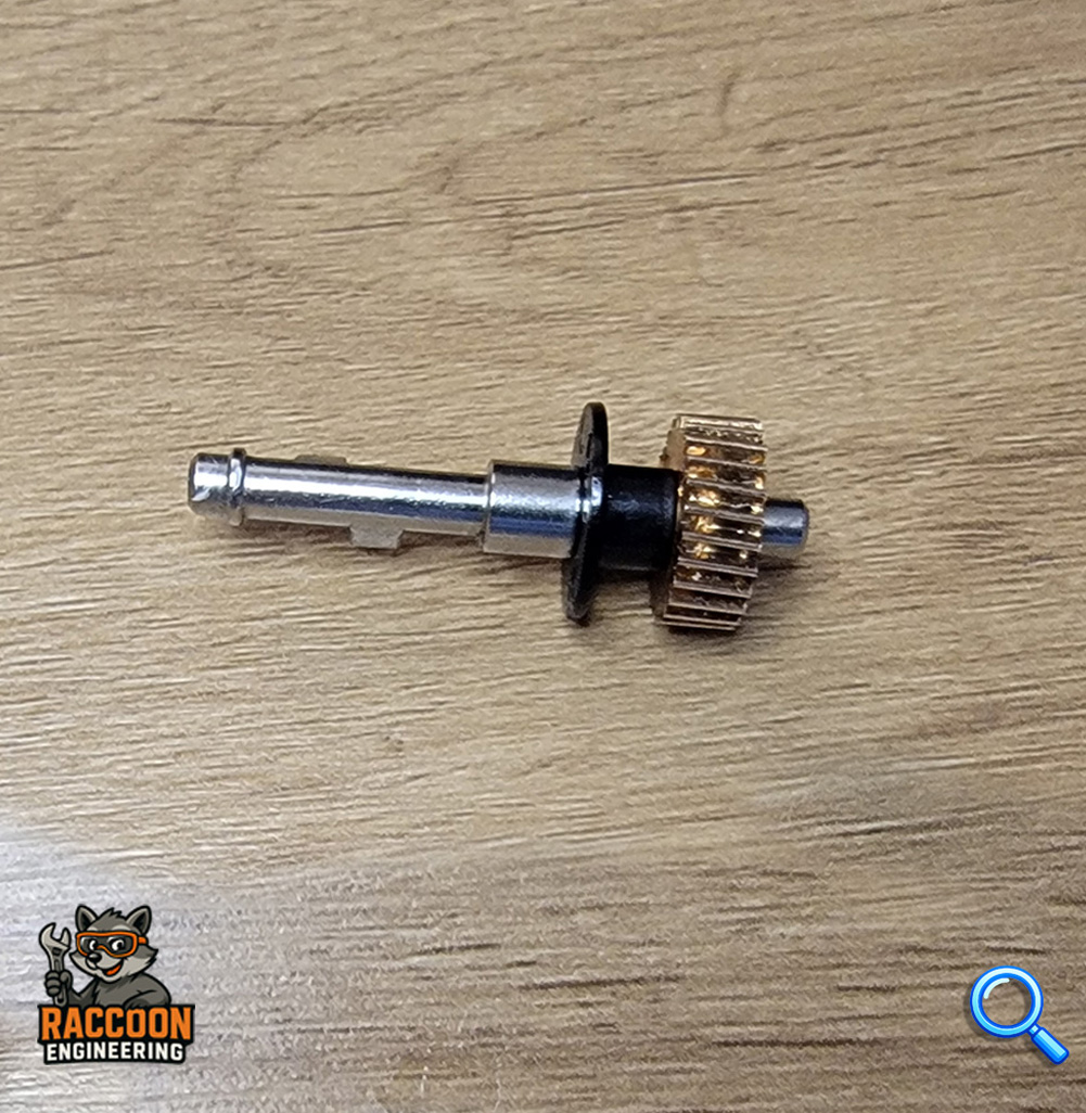
Camshaft
Located in the upper printhead between elastic arms. Driven by the shifting extruder. Just slips in loosely.
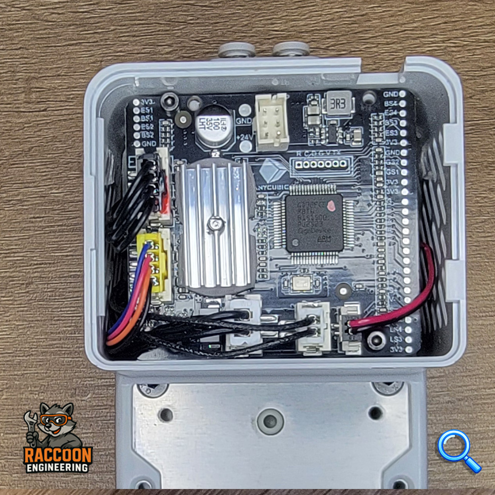
Driver Motherboard
Can be found on the back of the printhead under a snap on cover.
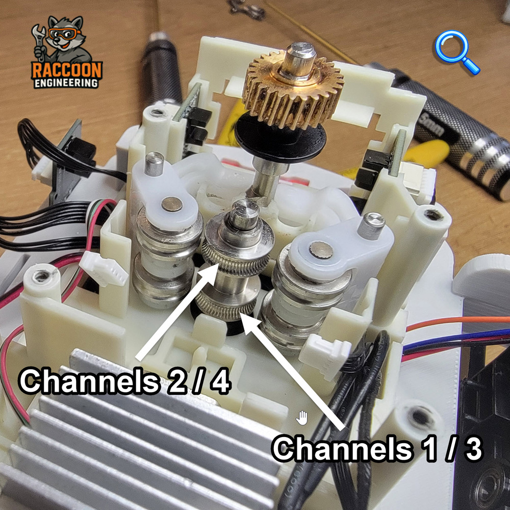
Extruder Gears
Fixed to Main Extruder Steppir Motor.
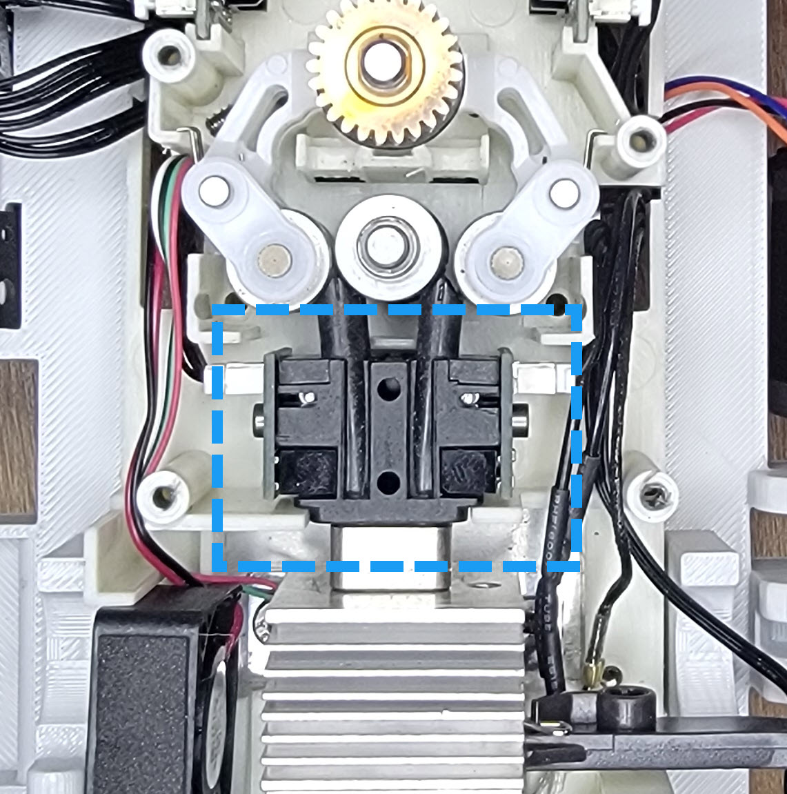
Filament Break Detection Board
Slips in between 4 into 1 cone and extruder gears. Wiring harness both sides.
Gear Position Detection Board
Slips in slot in shifting extruder frame. Final precise location set by tabs on back of front black display cover
Filament Break Detection Board
Slips in between 4 into 1 cone and extruder gears. Wiring harness both sides.
Hotend Cutter Assembly
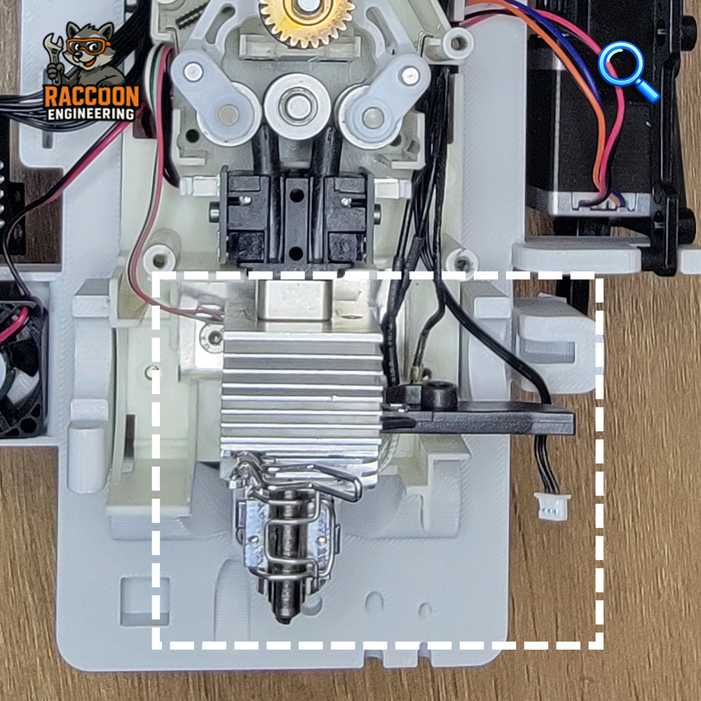
Attaches to metal backplate through the strain gauge. Contains 4 into 1 cone (and collar), strain gauge, heatsink, filament cutter, temp sensor, heating element and nozzle.
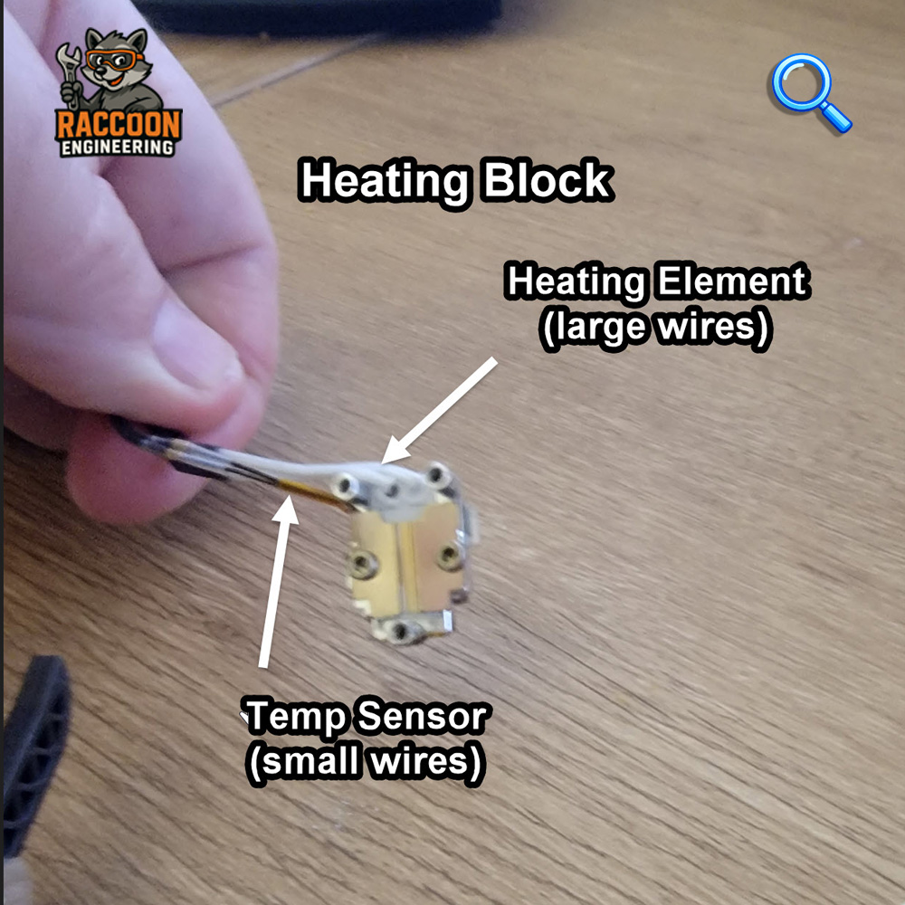
Heating Block
Contains Temp Sensor and Heating Element. Bolts to to lower heatsink with stand-offs. Fits loose when tightened by design.
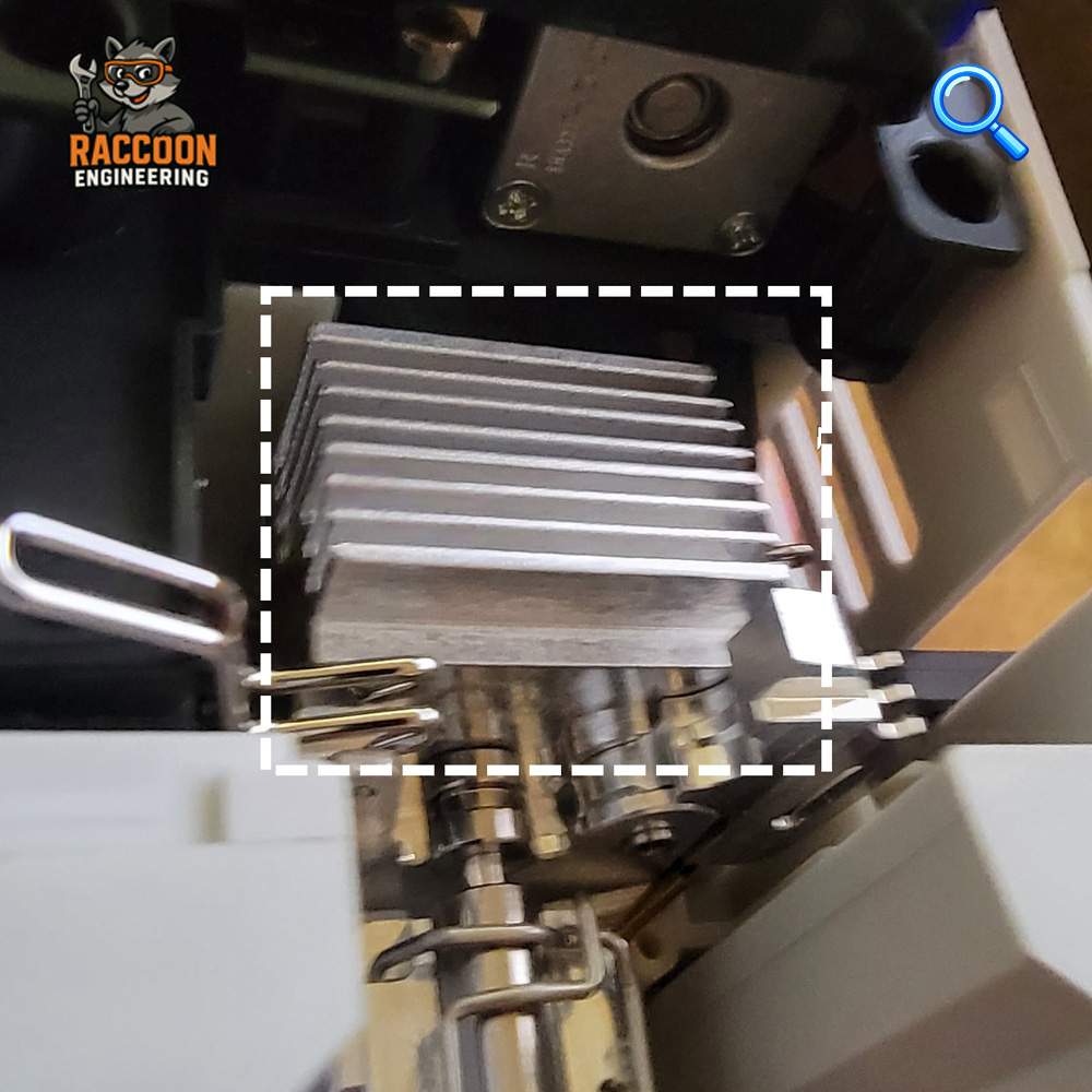
Heatsink
Part of Hotend Cutter Assembly. This attaches to strain gauge which in turn bolts to back plate.
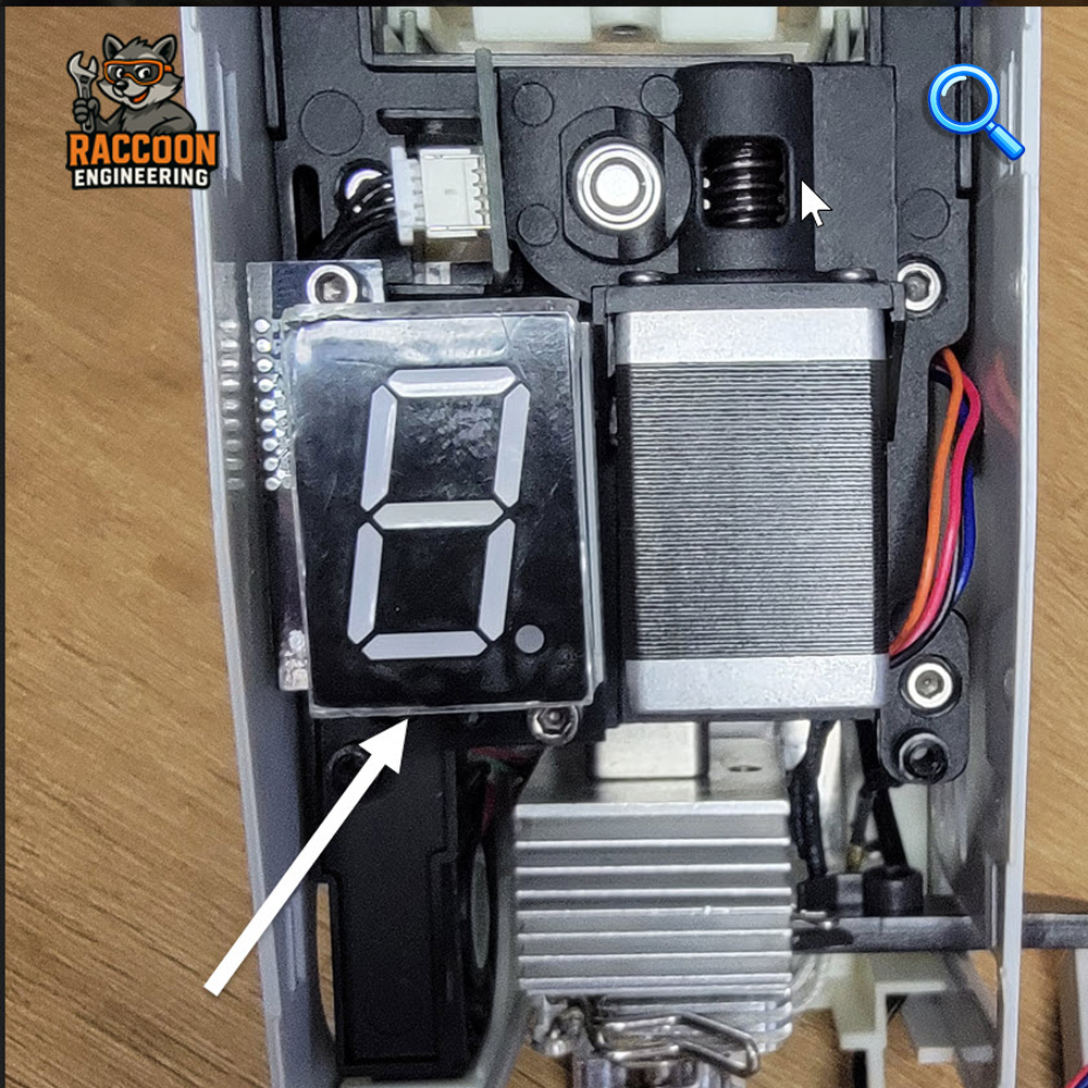
LED Channel Indicator
Part of Hotend Cutter Assembly. This attaches to strain gauge which in turn bolts to back plate. Attaches to Shifting Extruder Frame with two screws.
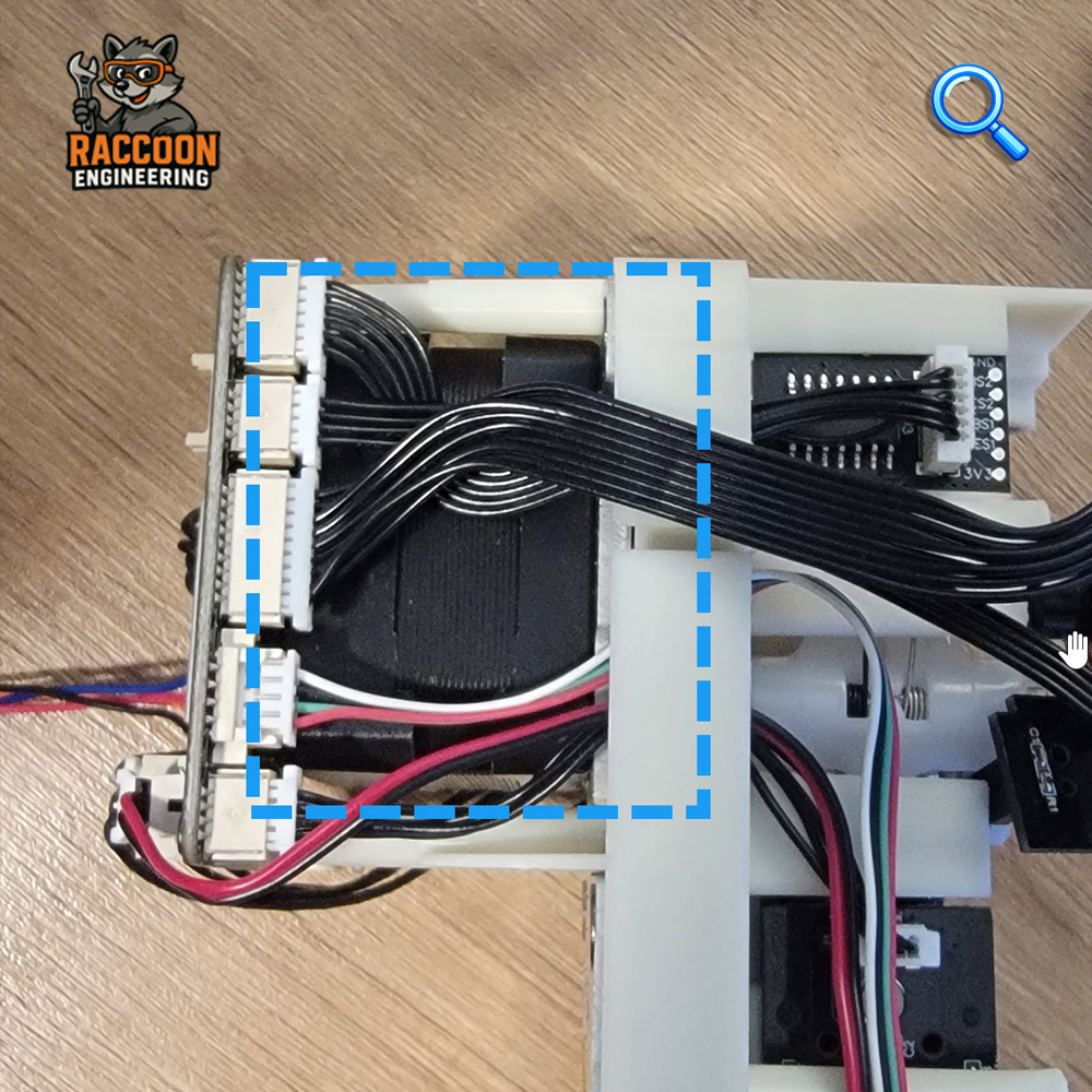
Main Extruder Motor
Mounts between backplate and driver motherboard. Extruder Gears are attached to motor shaft
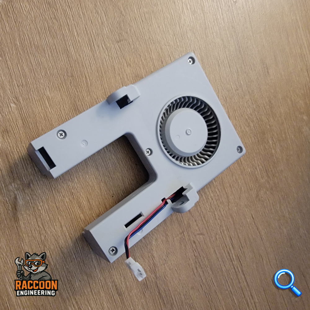
Model Fan
Connects to bottom of printhead with two 2mm allen screws. Wiring connector on inside to the right of hotend.
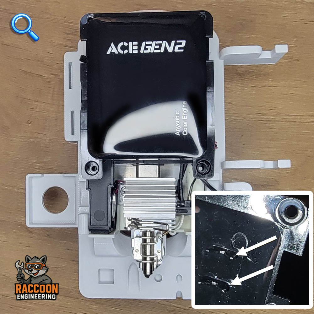
Front Cover
Attaches to front of printhead with four 2mm screws. Note "notches" on back which properly align gear position detection board.
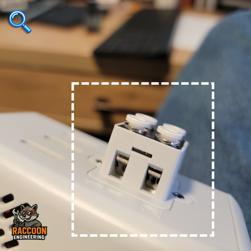
Upper Channel
Screws to top of printhead with two 2mm allen screws.
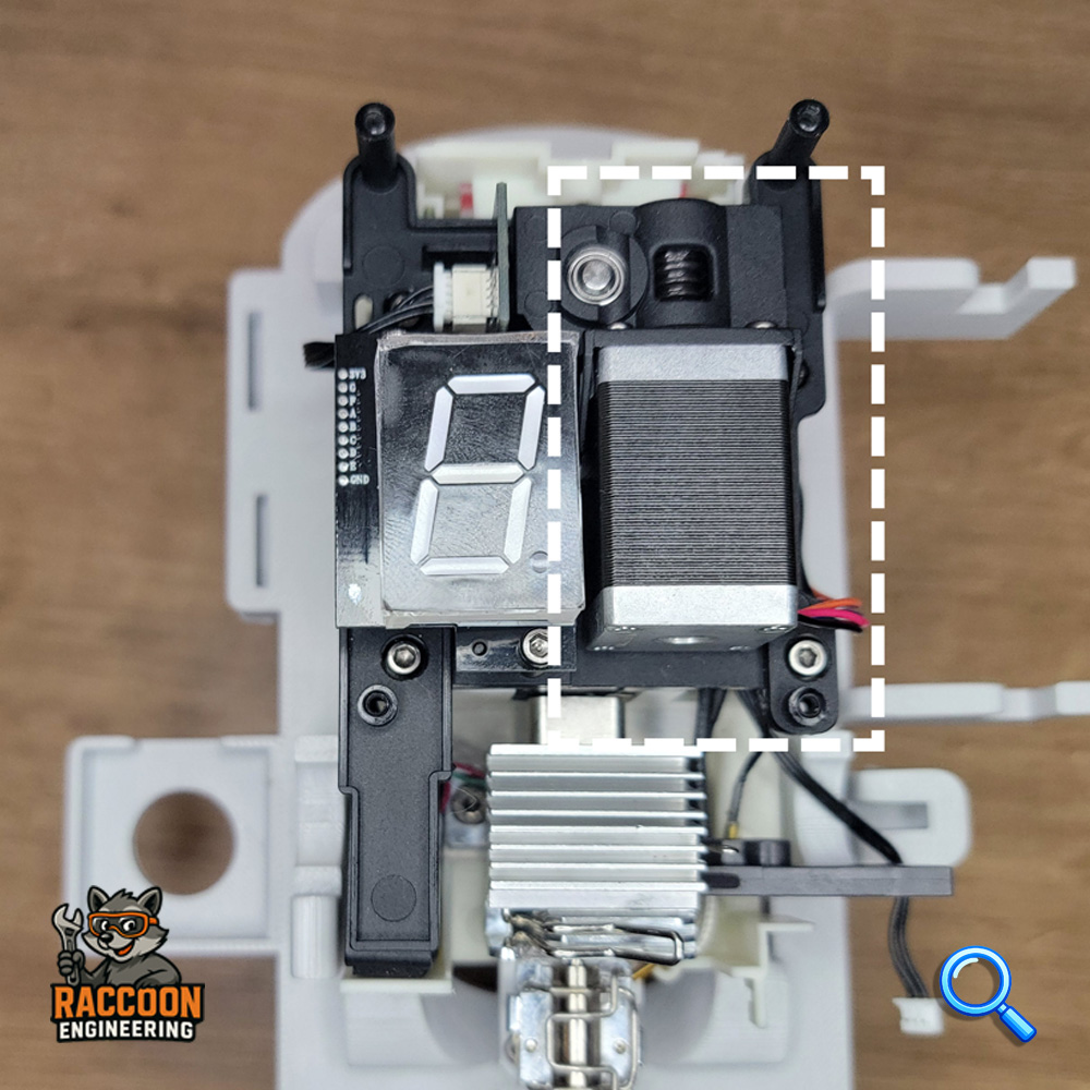
Shifting Extruder Motor
Attaches to front of printhead with four 2mm screws. Note "notches" on back which properly align gear position detection board.
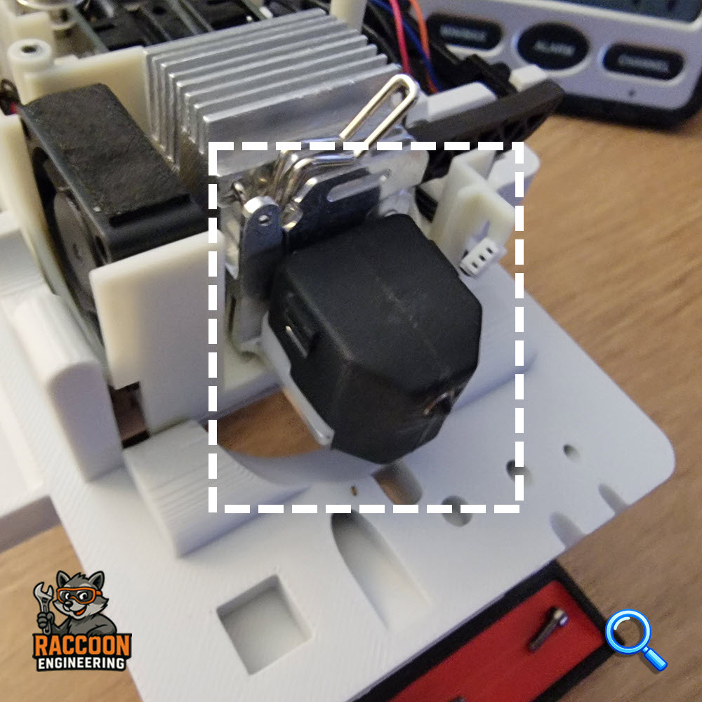
Silicone Sleeve (aka sock)
Snaps onto hotend.
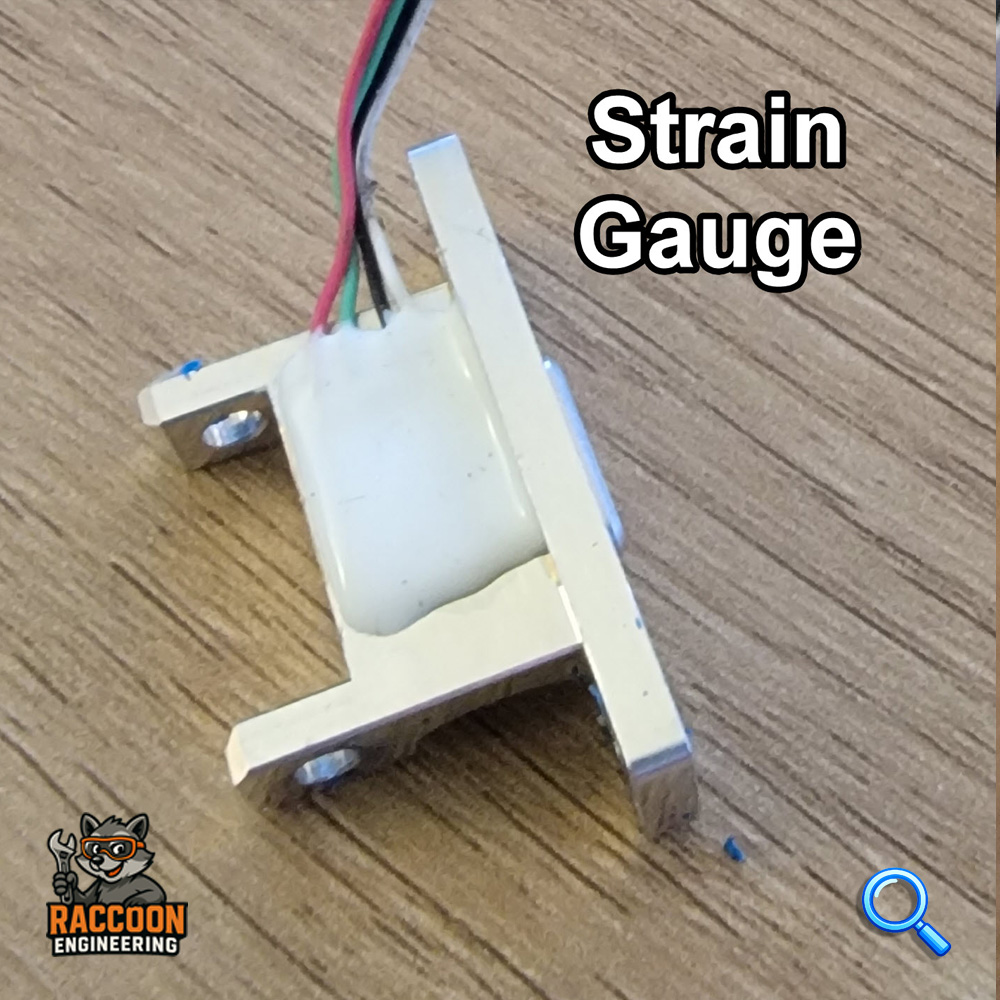
Strain Gauge
Attaches hotend cutter assembly to backplate. Has two 2mm screws to backplate and two into side of heatsink.
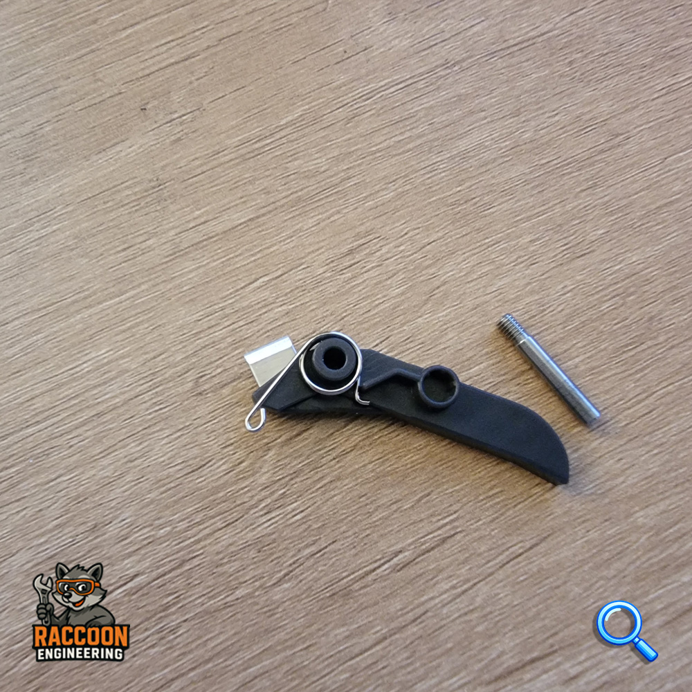
Filament Cutter
Held in place with 1.5mm shouldered pin accessible from bottom of heatsink.
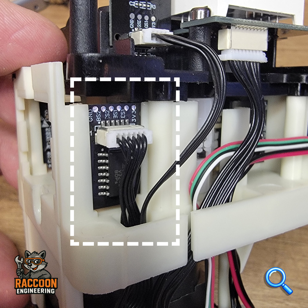
Upper Filament Detection Board
One on each side. Channel 1 and 2 board shown. Drops in slots on frame.