
Important: Power off printer
Replacing the Heating Bed
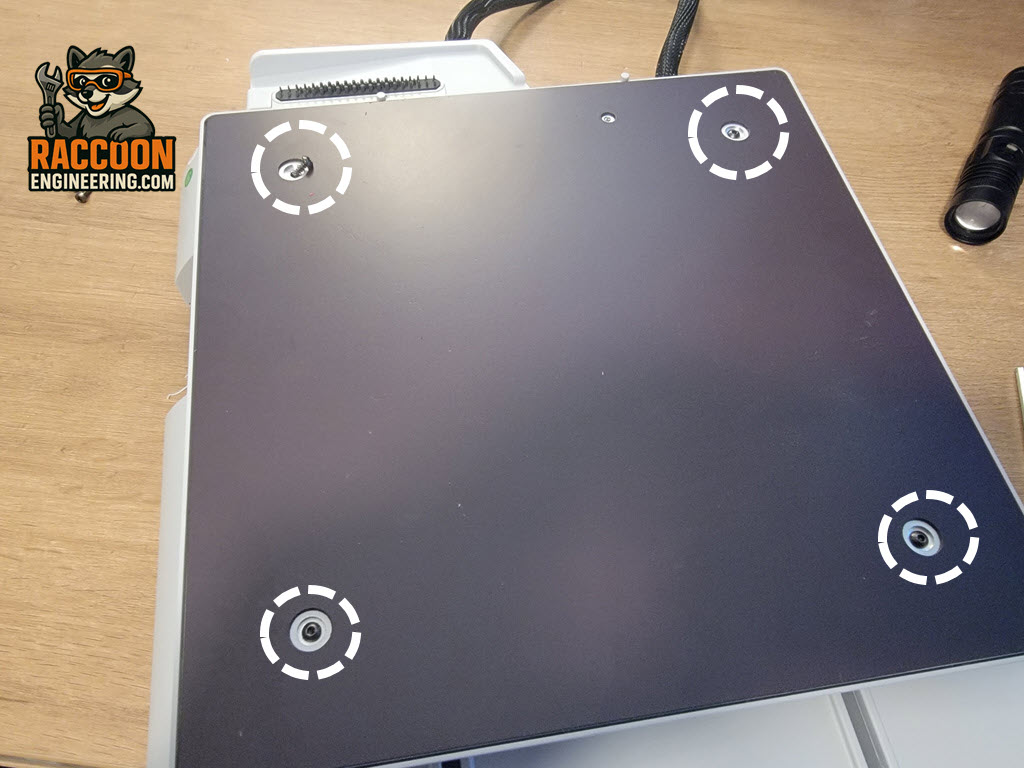
Using a 2 mm Allen driver, remove the four screws securing the heated bed assembly (Figure 1). Once the screws have been removed, carefully move the heat bed assembly to the side of the printer while leaving the wiring connected.
With the heated bed out of the way, remove the four bed springs located and set them aside in a safe location. These springs are easy to lose during service, so removing them now helps prevent them from being misplaced.
Next, flip the printer over and remove the bottom cover by following the Bottom Cover Removal procedure.
Disconnecting the Heated Bed
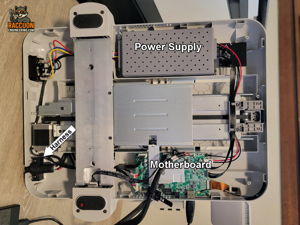
With the bottom cover removed, you will be working in three locations:
- Power supply connections
- Motherboard connections
- Harness strain relief at the rear of the printer
These locations are shown in Figure 2.
Power Supply
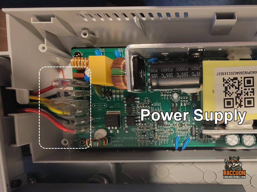
Remove the power supply cover, which is typically secured with two of the four cover screws. Once the cover has been removed (Figure 3), you’ll see that the low-voltage and data connections are located on the front of the power supply, while the AC input and heat bed output connections are located on the rear.
The heat bed power wires are the red and black wires connected to the terminals labeled L-OUT and N-OUT. These use spade connectors and can simply be pulled straight off the terminals.
Motherboard
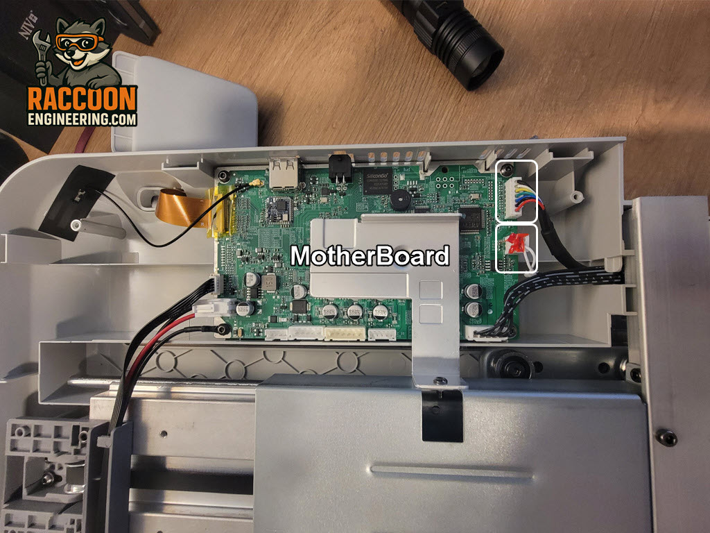
Next, disconnect the two heat bed harness connections from the motherboard (Figure 4):
- One 7-pin multicolor connector
- One 2-pin connector with two white wires
Important: The 2-pin connector is typically secured with adhesive. Carefully cut away as much of the glue as possible before attempting to remove the connector. Pulling on the connector while it is still glued in place can damage the motherboard or lift the connector from the board.
Harness Strain Relief
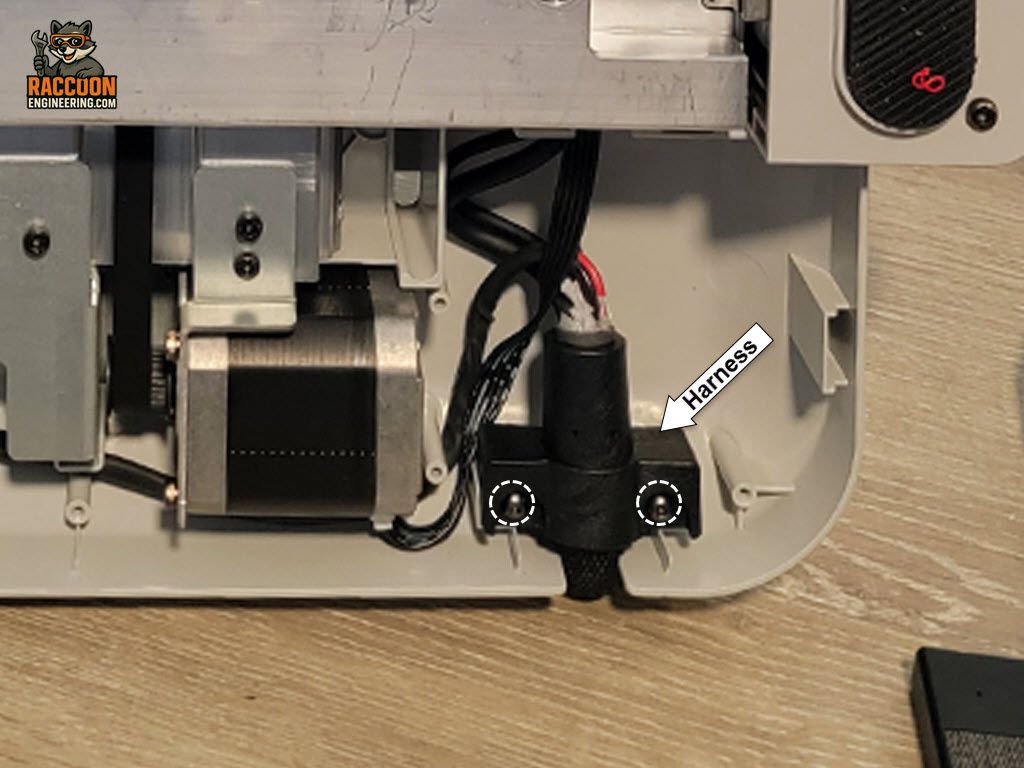
Finally, remove the harness strain relief from the rear of the printer by removing the retaining screws with a 2 mm Allen driver (Figure 5).
At this point, the heated bed assembly and wiring harness can be removed from the printer.
Installation is the reverse of removal.
When routing the new harness, make sure it follows the original path and is secured in the strain relief exactly as the factory installation. Verify that the wiring cannot rub against moving components and that there is enough slack to allow the heated bed to travel its full range of motion without placing tension on the harness.
Reconnect all motherboard and power supply connections, reinstall the power supply cover and bottom cover, reinstall the four bed springs, and secure the heated bed with the four mounting screws.
The above Service requires a full printer calibration.