
1000 Hour Maintenance
Best viewed on Desktop. This is a lot to unpack on mobile device
Regular maintenance helps keep the motion system smooth, reduces wear, and can prevent print-quality problems caused by contamination, dried lubricant, or improper belt tension.
This procedure covers lubrication, cleaning, and belt inspection/tensioning of the X, Y, and Z axes, along with printhead and purge ejector maintenance.
 As time goes on, we will add additional links to Brian Cabalic’s technical videos in the appropriate sections of this document. Look for this icon.
Required Items
Lubricants
- Recommended light machine oil: Super Lube oil Amazon Link
- Alternate oil: OilStick from Slant 3D (our personal favorite) Website
- Recommended grease: Super Lube grease Amazon Link
Cleaning Supplies
- Q-tips / cotton swabs
- Small brush or old toothbrush (or your significant other’s — Raccoon Engineering accepts no responsibility for the consequences)
- Isopropyl alcohol
- Clean, lint-free rags
- General-purpose cleaner for final cleanup
Tools
- 2 mm allen wrench
- 5 mm allen wrench
- 5 mm allen wrench
- Compressed air (canned is fine)
- Pointed cleaning pick, such as a dental pick (optional)
Raccoon Engineering Note: Grease vs. Oil
There are plenty of opinions about whether linear rods and lead screws should be lubricated with grease or oil.
At Raccoon Engineering, we generally prefer a light machine oil on exposed linear rods and lead screws. Oil is easy to apply, doesn’t collect as much dirt, and makes routine cleaning and relubrication much easier.
Grease works well where lubricant needs to remain in place for a long period of time, but it also tends to collect dust, dirt, filament debris, and other contamination. Over time, old grease can become dirty, hard, and caked onto the moving components. In the end, the choice is yours. Just apply your favorite lubricant.
Our rule is simple:
If you’re going to grease it, clean off the old grease before applying new grease.
More lubricant is not better. Whether using oil or grease, only a thin film is required.
Y Axis
The Y axis is the most difficult axis to properly service and will take the longest.
Anycubic describes applying grease to the rods with a brush through the gantry cover openings in the printer. While this may add lubricant, it does not allow the rods and rollers to be properly cleaned first and the grease distributed properly.
We prefer removing the bottom cover so the Y-axis components can be properly serviced.
1. Position the Printer
Power off and unplug the printer.
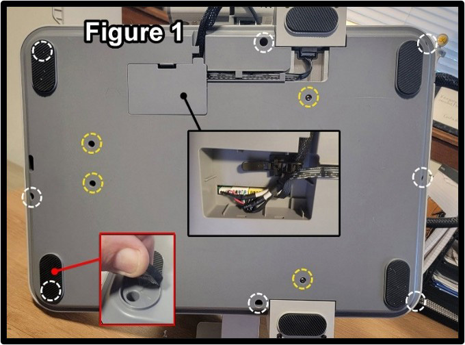
Carefully position the printer upside down so it rests on the front of the printer and the gantry.
2. Remove the Wiring Cover
Remove the wiring cover and disconnect the four wiring connectors underneath.
The connector leading to the Z-axis motor should also be unplugged at the motor, allowing the short wiring harness to remain attached to the cover.
3. Remove the Bottom Cover
The bottom cover is secured with 12 screws; see Figure 1:
- 4 machine screws (yellow circles)
- 8 plastic-threading screws (white circles)
All screws use a 2 mm allen driver.
The two outer screws at the front of the printer are hidden beneath the rubber feet. Lift the outer half of each foot to access these screws. Do not completely remove the rubber feet.
Remove the bottom cover.
4. Clean the Printer Base
Remove any filament pieces or other debris that may have fallen through the Y-axis slots.
Compressed air should generally not be necessary. Most debris will be loose and can simply be removed or allowed to fall out while the printer is positioned on its side or front.
5. Clean the Y-Axis Rods
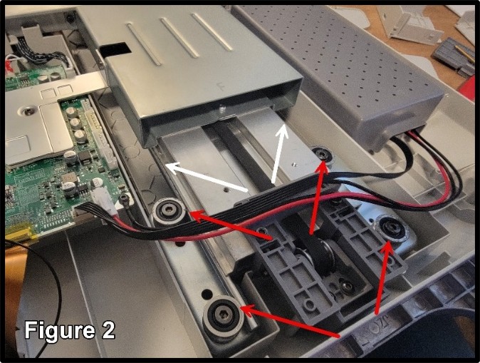
The bed travels on linear rods that are only partially accessible. Figure 2 shows the linear rods with white arrows and rollers with red arrows.
Using a small rag dampened with isopropyl alcohol, wipe the exposed portions of the rods while moving the bed back and forth.
Continue moving the bed and cleaning the rods to remove as much of the old grease and contamination as possible.
6. Clean the Rollers
Clean the roller wheels attached to the bed frame as shown by red arrows.
A Q-tip soaked with alcohol works well for reaching these areas.
Continue moving the bed as necessary to expose different portions of the rollers.
7. Lubricate the Y Axis
Apply a thin layer of grease only to the outer working surface of the rods.
There is no benefit to coating the entire circumference of the rods because the rollers only contact the outside working surface. Excess grease simply attracts contamination and makes the next service more difficult.
Apply a very small amount of grease to the roller contact surfaces and move the bed forward and backward several times to distribute the lubricant.
Although we generally prefer oil on linear rods, grease is the most practical lubrication method for the Y axis because of its design and limited accessibility.
8. Inspect the Y-Axis Belt System
While the bottom cover is removed, take a moment to inspect the Y-axis belt, motor, idler, and tensioning mechanism.
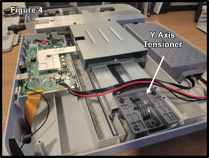
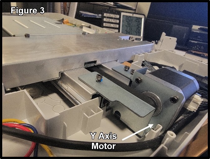
The Y-axis motor is located at the rear of the printer, while the tensioning mechanism is located at the front. (figure 3 and 4)
Actual belt tension adjustment will be performed after the printer is reassembled but now is a great time to get a feel for how it works.
9. Reinstall the Bottom Cover
Reinstall the bottom cover and securely reconnect all wiring harness connectors.
Make certain every connector is fully seated before returning the printer to its normal position.
X Axis
The X axis requires considerably less work.
1. Clean the Crossbar
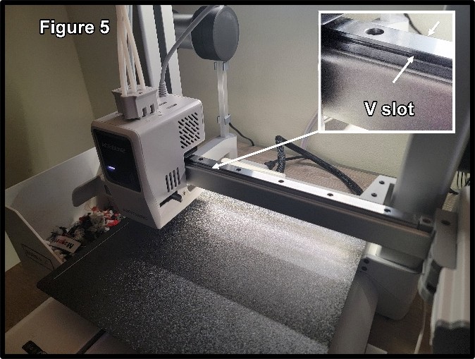
Wipe the X-axis crossbar thoroughly with isopropyl alcohol to remove dust, grease, and other contamination.
Pay particular attention to the V-shaped front and back running surfaces shown in Figure 5.
2. Lubricate
Apply a very light film of oil to:
- Front V-slot
- Rear V-slot
- Small amount to top sliding surface
Move the printhead back and forth across the X axis 5–10 times to distribute the oil.
Using a clean lint-free rag, wipe away any excess.
The goal is to leave a microscopic lubricating film — not a visibly wet rail.
Z Axis
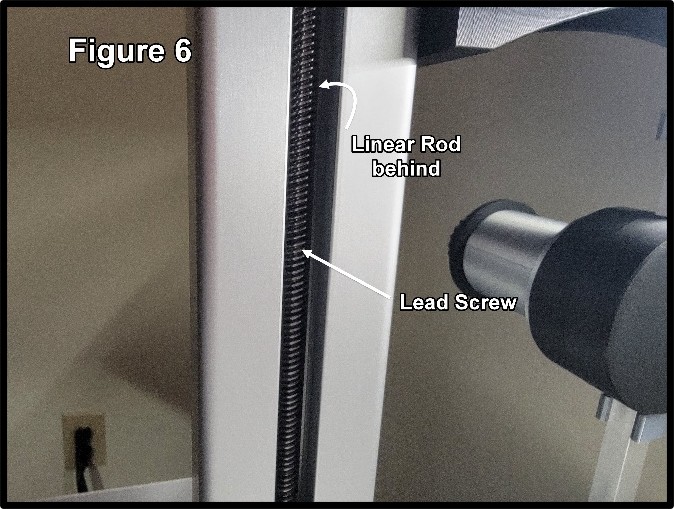
The Z-axis system consists of:
- Two lead screws
- Two linear guide rods
- Cross belt to keep both sides in time.
The linear rods are positioned directly behind the lead screws (Figure 6) and are largely hidden from view. Anycubic does not specifically mention servicing these rods, but they can be lubricated using a bent Q-tip and light oil.
1. Clean the Lead Screws
Use a small brush and isopropyl alcohol to clean the Z-axis lead screws.
Rotate the lead screws manually by pulling the Z-axis belt located in the upper crossbar sideways as you clean.
Work from top to bottom until the threads are clean and the old grease and contamination have been removed.
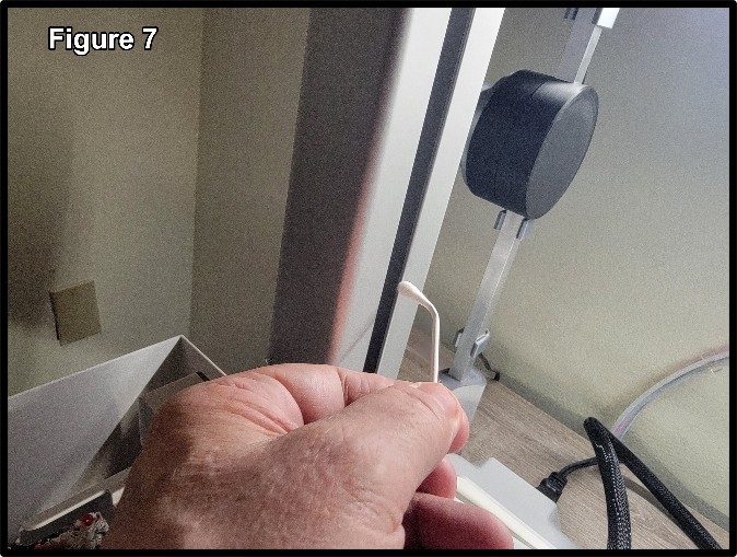
2. Lubricate the Hidden Linear Rods
Apply a small amount of light machine oil to a Q-tip.
Bend the Q-tip slightly so it can reach around the lead screw and contact the hidden linear rod, as shown in Figure 7.
Apply a thin film of oil to the rod from top to bottom.
Repeat on the opposite side.
3. Lubricate the Lead Screws
Grease is commonly recommended for lead screws and is perfectly acceptable when properly maintained.
Raccoon Engineering prefers light machine oil to be applied more frequently, primarily because it is easier to clean and is less likely to accumulate dirt and debris.
Regardless of whether you choose oil or grease:
Use only a light coating.
Excess lubricant does nothing except collect contamination.
Belt Inspection and Tensioning
At 1,000 hours, inspect all belts for:
- Fraying
- Cracking
- Damaged or missing teeth
- Unusual wear
- Contamination
- Belt tracking problems
Do not assume that tighter is better. Excessive belt tension can increase bearing and motor loads and may create print-quality problems of its own.
X-Axis Belt Tensioning
Remove the left-side cover.
The cover is secured by a single 2 mm Allen screw located at the rear.
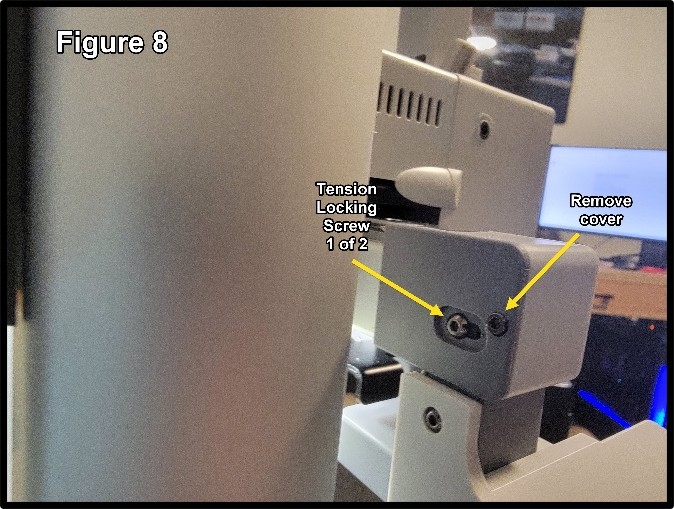
You will be working with three screws (figure 8)
The center spring compression screw is NOT used to set belt tension. Its purpose is to compress the tensioning spring when removing or installing the belt.
However, this screw must be loose before tensioning the belt.
With a 2 mm Allen wrench, loosen the two 2 mm tension-locking screws. One is located on the back and one on the top.
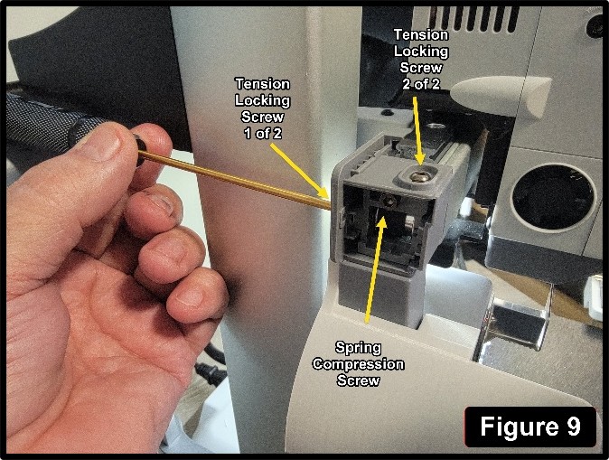
Using a 2.5 mm Allen wrench, loosen the 2.5 mm screw to allow the belt to tension ( figure 9).
Move the printhead slowly from side to side several times to allow the belt to settle.
Tighten the two tension-locking screws.
Turn the center spring compression screw inward until it just contacts the housing.
Do not tighten it.
The X-axis belt is now tensioned.
Y-Axis Belt Tensioning
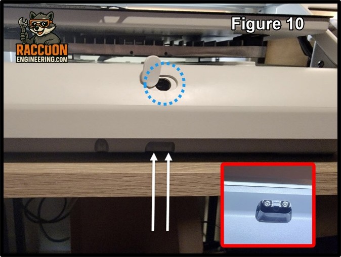
You will again be working with three screws (Figure 10).
The center spring compression screw does not tension the belt. It compresses the tensioning spring for belt removal and installation.
It must be loose before setting belt tension.
1. Release the Compression Screw
Using a 2.5 mm Allen wrench, back out the center spring compression screw located beneath the rubber plug.
2. Release the Tensioner
Using a 2 mm Allen wrench, loosen the two tension-locking screws located on the bottom of the printer.
The spring will automatically move the idler into the proper position and establish belt tension.
3. Settle the Belt
Slowly move the bed from front to back several times.
This allows the belt to settle naturally on the pulleys and idler.
4. Lock the Tension
Tighten the two tension-locking screws.
Turn the center spring compression screw inward until it just contacts the housing.
Do not tighten it.
The Y-axis belt is now properly tensioned.
Z-Axis Belt
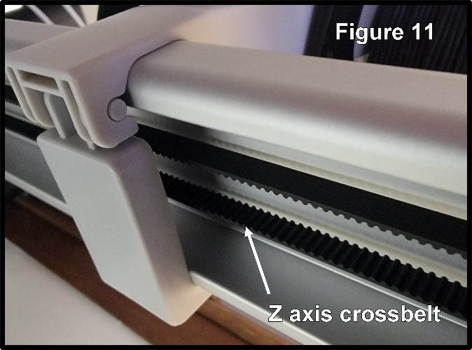
Unlike the X and Y axes, the Z-axis belt does not use a spring-loaded tensioning mechanism.
Because the Z axis also experiences considerably less belt travel, we do not recommend adjusting Z-axis belt tension
as part of routine 1,000-hour maintenance unless there is a specific reason to do so.
Inspect the belt for damage, wear, tracking problems, or obvious looseness.
If no problem is present, leave the tension alone.
Printhead Maintenance
Remove and disassemble the printhead by following Brian Cabalic’s printhead service video.
We have a technical document covering the entire printhead which can be found here.
It is recommended you download and print Brian’s Printhead Service Jig available here.
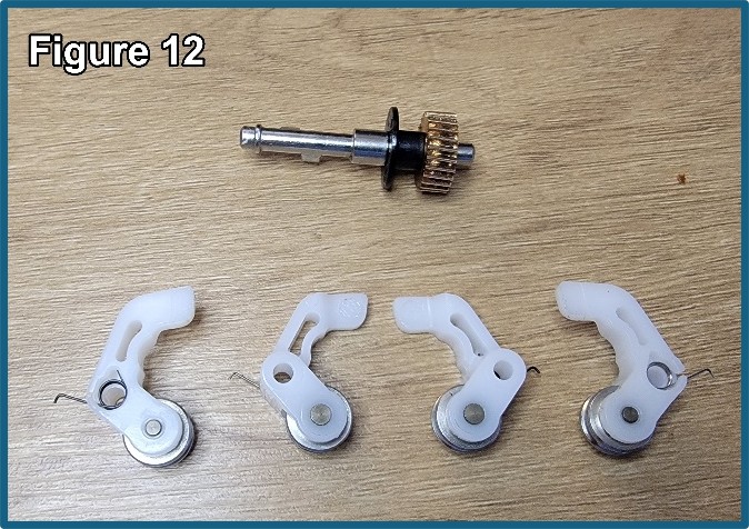
1. Clean the Cam Mechanisms
Clean the cam arms, rollers, and camshaft with isopropyl alcohol and a clean rag (Figure 12).
2. Clean the Extruder Gears
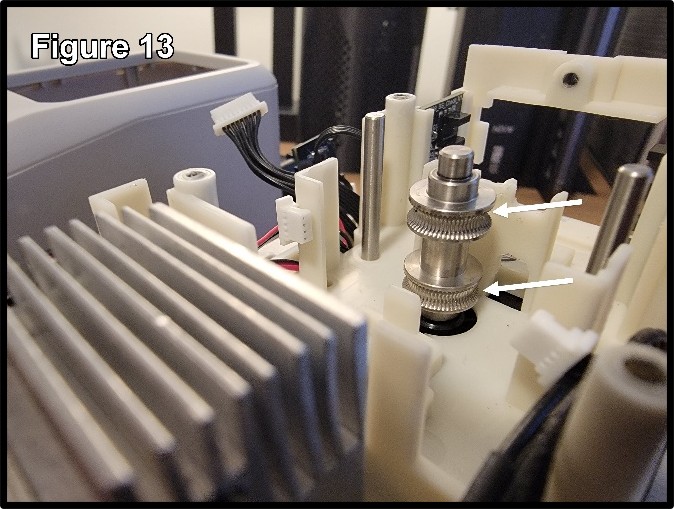
Inspect the extruder gears closely for dirt and filament dust (Figure 13). Clean them with compressed air and, if necessary, a small stiff brush or a pointed cleaning tool such as a dental pick.
Use compressed air to remove loose debris from the remainder of the printhead.
Optional: Lower Break Detection Block
The lower break detection block can be disassembled and blown out with compressed air; however, it contains four tiny
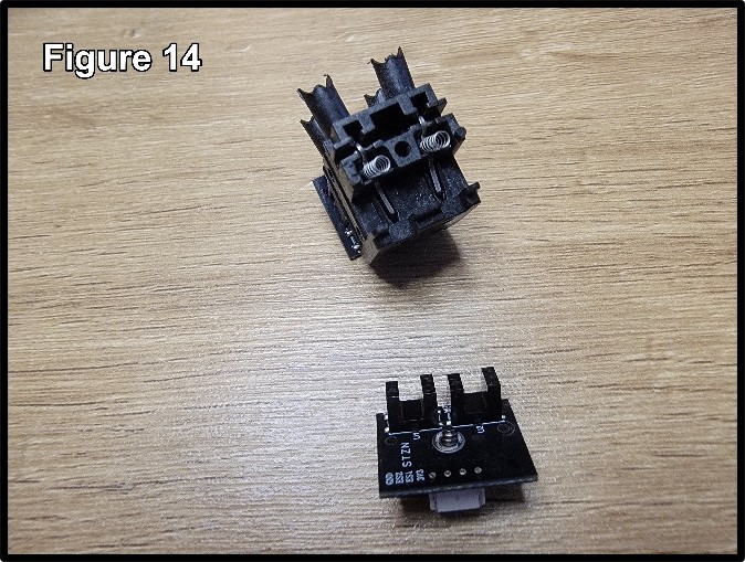
springs and four tiny arms that are easily lost.
Proceed with caution if you choose to disassemble this block (Figure 14).
3. Clean the Hotend/Cutter Assembly
Loosen the set screw in the side of the heatsink and slide out the 4-into-1 cone (Figure 15).
Remove the small collar located beneath the cone. Inspect both the collar and the cone for debris and clean them as necessary.
Remove the nozzle and blow compressed air through the heatsink to make certain the filament path is clear. Reinstall the collar
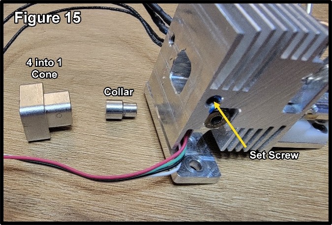
and 4-into-1 cone, then secure the set screw.
4. Lubricate the Moving Components
Apply only a light film of grease to the following components, as indicated by the blue arrows in Figure 16:
- Camshaft lobes
- Cam-arm pivot shafts
- Small gear on the camshaft
- Gear on the shifting-extruder stepper motor
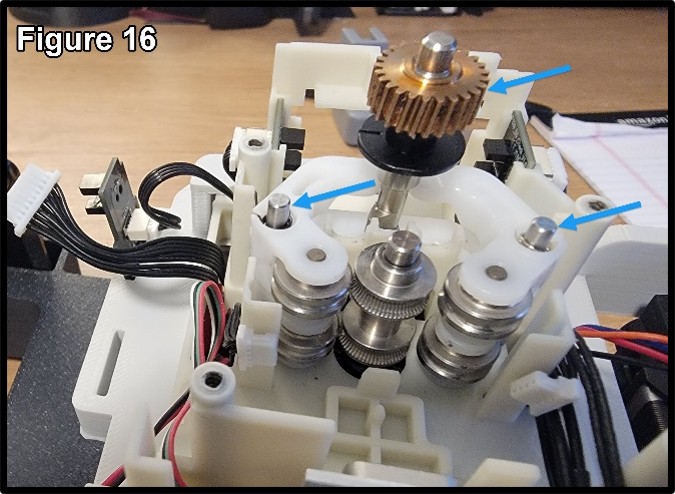
Do not apply lubricant to the extruder gears or filament path.
5. Reassemble the Printhead
Reassemble the printhead by following Brian’s video.
Purge Ejector Maintenance
1. Remove the Purge Ejector
Remove the single 1.5 mm screw from the back of the purge ejector, then slide the ejector off the printer.
2. Remove the Bottom Cover
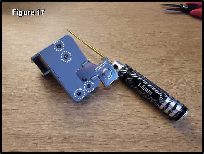
There are five 1.5 mm screws on the bottom. Remove the four screws securing the plastic cover (Figure 17).
It is not necessary to remove the single screw securing the metal plate.
3. Inspect and Clean the Mechanism
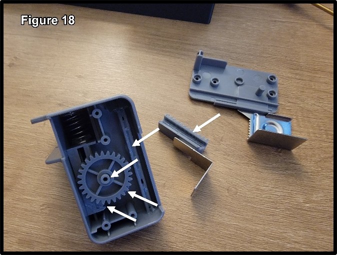
With the cover removed, the racks and gear will be visible. Remove the top rack with the metal ejector ram and remove the gear exposing the lower rack. Inspect the components for debris or damage.
Clean the components as necessary before lubrication.
4. Lubricate and Reassemble
Apply a small amount of grease to both rack gears, the rack slides on the underside, and the round gear. The locations are shown in Figure 18.
Reassemble the purge ejector in reverse order and reinstall it on the printer.
Final Cleanup
Once lubrication and belt maintenance are complete:
- Verify that all covers and screws have been reinstalled.
- Verify that all wiring connectors disturbed during service are fully seated.
- Move the bed and printhead by hand to confirm smooth movement.
- Inspect the printer for excess oil or grease.
- Wipe down the printer with a clean rag and appropriate cleaner or isopropyl alcohol to remove fingerprints, grease smears, and excess lubricant.
- Reconnect power and start the printer.
- Run the full calibration procedure before returning the printer to service.
One Last Raccoon Engineering Rule
If you can see lubricant dripping, running, or collecting in blobs, you used too much.
Lubrication belongs on the working surfaces — not on the covers, belts, electronics, table, floor, or the raccoons.